555 Timer Circuit Printable Schematic – With this information you will learn how how the 555 works. It is invented in 1971 by an american company signetics. There are a lot of applications of this ic, mostly used as vibrators like,. 555 timer block diagram • pin 1.
How Does Ne555 Timer Circuit Works Datasheet Pinout
555 Timer Circuit Printable Schematic
This tutorial provides sample circuits to set up a 555 timer in monostable, astable, and bistable modes as well as an in depth discussion of how the 555 timer. Additional • timing from microseconds through hours. A timer circuit performs two functions:
The Equivalent Circuit, In Block Diagram, Providing The Functions Of Control, Triggering, Level Sensing Or Comparison, Discharge, And Power.
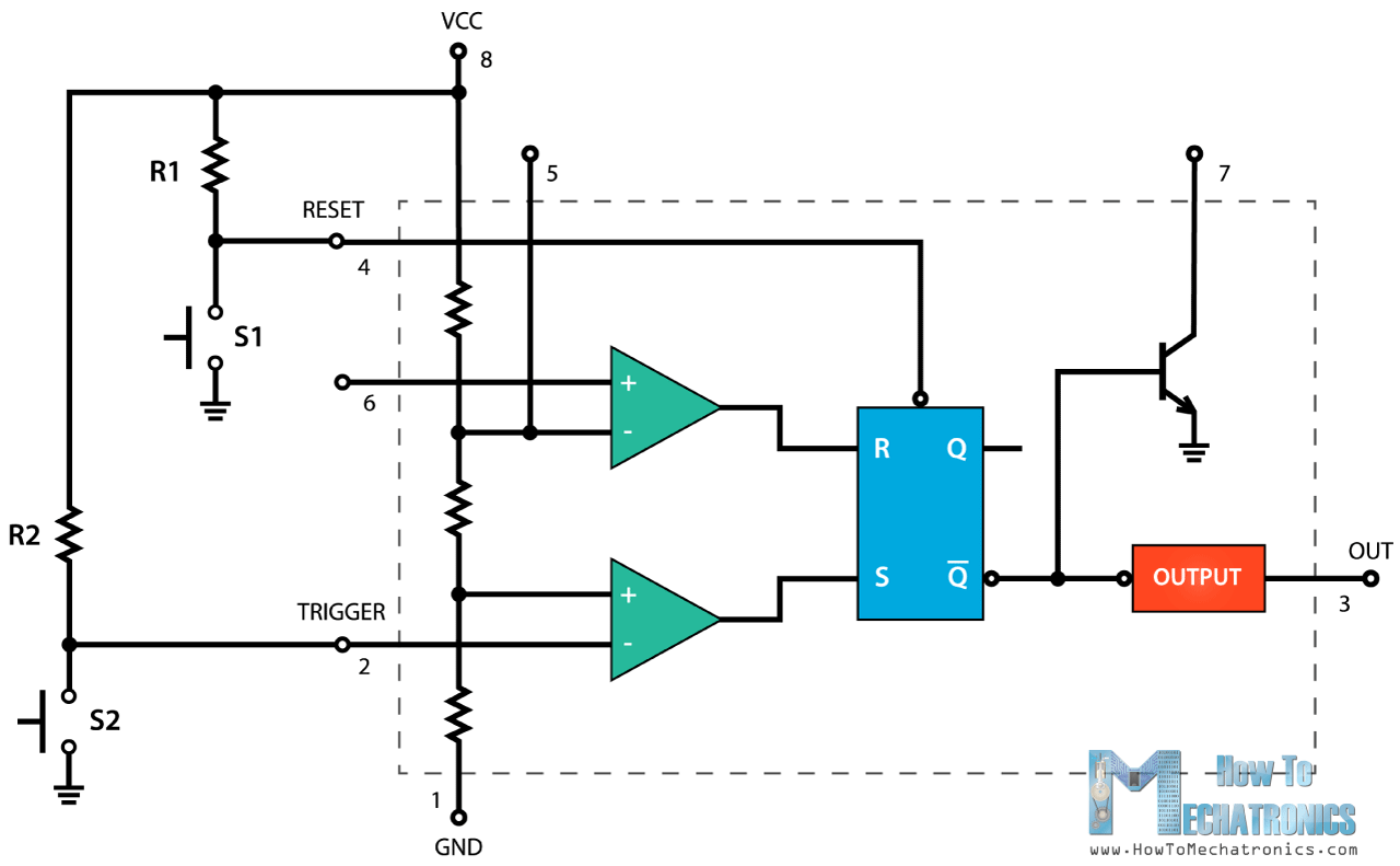
2 diodes, depending of the manufacturer. 555 timer ic is one of the commonly used ic among students and hobbyists. To understand the basic concept of the timer.
March 18, 2017 Byanusha 555 Timer Is An Industrial Standard Ic Existing From Early Days Of Ic.
555 timer +v gnd thresh ctrl the various inputs and outputs of this circuit are labeled in the above schematic as they often appear in datasheets (”thresh” for threshold, ”ctrl” or ”cont” for control, etc.). Learn how to use the 555 timer to make fun projects like blinking lights, synthesizers, alarms+++ with circuit examples and component lists. The basic 555 timer circuit diagram and its working are explained in this article.
The Lm555 Is A Highly Stable Device For Generating 1• Direct Replacement For Se555/Ne555 Accurate Time Delays Or Oscillation.
Output stays either high or low, until forced to change. The below list from circuit digest consists of a huge collection of 555 timer circuits with neat circuit diagram and practical diy hardware explanation enabling you. A mechanism for generating the delay, and a.
To Use The 555 Timer As An Astable Multivibrator, Simply Connect It To A Capacitor, A Pair Of Resistors, And A Dc Power Source.
Basic bistable 555 timer circuit schematic diagram by electronzap. Learning the 555 timer is a simple integrated circuit that can be used to make many different electronic circuits. A standard 555 chip includes 25.
Its Name Is Derived From Three 5K Ohm Resistors ,Connected In Series Used In It.the.

How does NE555 timer circuit works Datasheet Pinout

Reverse engineering the popular 555 timer chip (CMOS version)

555 Timer IC Pin Diagram Features And Applications 555 Timer working

Dancing Light using 555 Timer
Ne555 Transistor Driver

Introducing 555 Timer IC Tutorial Random Nerd Tutorials

How to Read Electrical Schematics Circuit Basics

1 to 15 Minute Timer Circuit Diagram, Working and Applications

Analysis of 555Based PWM Circuit Math Encounters Blog

555 Timer Schematic / Integrated Circuit Schematic Edwards Coull1952

Schematic 555 Timer Circuit Diagram / LM555 Electronics Schematic

Digital Stop Watch The Circuit

555 Timer Schematic 555 Timer Circuits In Proteus In this category

Ne555 Transistor Driver

Adjustable Timer Circuits Using IC 555